{ [ ] Projects >>> [Hardware] - [Software] - [Class] - [Other] - [Failed] -|!|!|- [Resources] - [Biography] - [Contact] - [ ] }
This project was for my CS120B (intermediate embedded systems) lab final. It was a solo project by choice. Below is my lab report, and videos.
8 March 2011
www.cs.ucr.edu/~lewisc
Stingray Robot Game Report
This report details the hardware and software used in the Stingray robot game project completed for CS120B in Winter 2011.
Introduction
For this project I implemented a mobile robot game. The user wirelessly drives the robot through the playing field by using two joysticks configured in a traditional tank drive fashion. The objective of the game is to collect all the RFID tags as fast as possible.
Hardware
There are two main units: the base station and the mobile robot. The base station has user interface components, and is stationary. The robot portion has a robot that can roam around and do user defined tasks. These two units communicate through a wireless link.
Both the robot and the base station use a Parallax P8X32A microcontroller (also known as a "Propeller").
Base Station
The base station uses two joysticks for user input. The joysticks are standard PS2 style joysticks set up as voltage divider circuits. The voltage is then fed into a channel on the MCP3208 analog to digital converter. Each joystick has three modes of input: vertical motion, horizontal motion, and a select button. This project uses two of the modes: vertical motion and the select button.
For output, the base station produces an NTSC signal on the output. This TV style signal is fed into a small LCD screen, and is used to display feedback such as user instructions, current game time, tags collected, and final score.
The last component in the base station is an XBEE module, configured to be a drop in wireless replacement at 57600 baud. The XBEE module has many advanced configuration and networking options, here it is used in almost the factory configuration (the baud rate is higher).
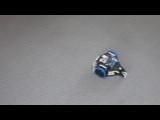
Mobile Robot
The robot chassis is a Parallax Stingray robot. The motors have been switched down in gearing to a 50:1 gearing ration (175 rpm at rated voltage) instead of the stock motors (~350 rpm at rated voltage). This allows for easier human control, since the higher speed motors are much faster and more sensitive to user error. The motors have also been fitted with optical encoders, although they are not utilized for this project.
The robot also uses a Parallax RFID reader. This reader is mounted to the bottom of the chassis, and is used to “collect” the RFID tags in the game. The reader is likely the largest source of problems in the design. The reader is slow, even on a scale noticeable by humans. In addition, the cards have to be precisely positioned in order to read them. Together, sometimes it is frustrating to the user to collect a card. Some software fixes have been applied that help mitigate this problem, but in some cases it may still be noticeable.
Finally, the robot uses an XBEE with the same configuration settings as the base station. Originally, a much simpler 912MHz radio transceiver was tested, but it was found to have buffer overflows approximately every 15 seconds. This led to the robot halting all motion for approximately 2 seconds. This issue was seen before the RFID data transmission was implemented (which would have exacerbated the buffer overflow). Due to this, the faster 2.4 GHz XBEE modules were selected.
Software
The software details can be seen in the code. Given here are high level comments and code structure.
The game code implements four sections in parallel (although several others are executing in parallel behind the scenes as well). The base station has code that will read in user input and transmit it on the com link, and code that gets input from the com link and processes the data. The mobile robot has code to take user control information from the com link and run the motor control filtering algorithms before directly controlling the motor. The robot also has code to interface to the RFID reader. This portion of the code is essential, because it helps to mitigate some of the shortcomings of the RFID reader discussed above.
Each parallel portion of code described above is disjoint from each other portion, except for messages passed. All communication between portions is either user inputs, or RFID tag readings. This allows for better and faster debugging of issues, since one portion of the code can be developed and tested in an orthogonal manner relative to the other portions.
Conclusion
This project was a challenge to implement due to the many different devices used and the raw motor control methods available. However, a suitable control algorithm for the motors was found, component limitations were mitigated, and overall the final game is both fun and challenging. Through user trials with a variety of individuals, testers were constantly engrossed in the game and it's challenges.
Downloads
Code and report - cs120b_lab_final.tar
Movie -
(c)2010 Cody Lewis
lewisc@cs.ucr.edu