CS120B
Lab EXAM (www.cs.ucr.edu/~sneema/prof/ta/final.htm)
Emulation of a Roulette
Wheel
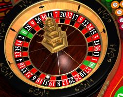
In this lab you need to develop a circuit in VHDL which will emulate a roulette wheel. In roulette, a wheel spins and a small ball bounces from place to place finally coming to rest in one of the slots. In a standard wheel (pictured below) there are 18 red slots, 18 black slots, and two green ones ( 0 and 00 on the top and bottom of the wheel respectively). The wheel alternates red and black numbers. The numbers do not follow a "standard" counting.
Implementation idea
Wheel: The wheel itself is going to be emulated by a free running
counter which is going to iterate through the wheel count sequence.
Ball: The ball (or the value taken from the wheel) will consist of two
modules. The first is a register which will capture the value of the wheel at
specific times. The second module is a "spinner" wheel which creates a
pulse of clock enables for the register to capture the value of the wheel.
|
|
The Modules:
(Point Distribution 30 + 30 + 20 + 20 + Bonus 5 =
100 + 5) (It is not required to match the exact timings, just get the
characteristics of the waveform correctly)
(1) RCOUNTER: This is the freewheeling counter. At every
positive edge of the clock it outputs the next number and color in the sequence.
Code the numbers as integers and colors as std_logic_vector(1 downto 0) .
G0 is 10, G00 is 01, R is 00, B is 11
Here are the numbers in sequence
(and their hex values too in case you need them)
conversions
Here is the testbench and expected
waveform.
(2) SPINNER: On the positive edge of the start signal the spinner outputs
5 pulses of time period 10 times that of the input clock. (This simulates the
ball bouncing 5 times, the time period simulates the time the ball is in the
air). The finished flag goes high as soon as start is asserted and remains high
until the 5 pulses are produced.
Here is the testbench and the expected waveform
(3) ROULREG: The outclock of the spinner acts as the latch enable for this
register. At the positive edge of the enable signal the roulreg reads in the
roulnum and roulcol from the rcounter and outputs it.
Here is the testbench and the expected waveform

(4) The Toplevel design wires the above components. The final value
(ball comes to rest) is indicated by the color and number when the finished flag
goes low.
Here is the testbench and the
waveform
(5) Bonus : We simulated the ball bouncing using the "spinner" module, but it was assumed that the ball is in the air for the same time for all bounces. Modify the spinner such that the 5 pulses gradually come closer (time period reduces) simulating the slowing of the wheel.