
|
|
|
|
[
Main ::
Calendar ::
Groups ::
Readings ::
Topology Generator ::
Final Binder ::
FAQ]
|

|
In this section we will talk a little bit more on the some technical aspects of your network as well
as the topology generator. First of all we need to mention that there are 2 ways of
deploying the narada nodes.
The first way is by emulating intermediate routers and the second is without emulating intermediate routers.
After discussing with your professor we decided to allow you to make your own choice on which alternative
to use. We just mention that the alternative of deploying your nodes without emulating intermediate routers
is easier to deploy and hence we recommend you to go with this approach.
In the following description we will help you understand how to implement the second alternative.
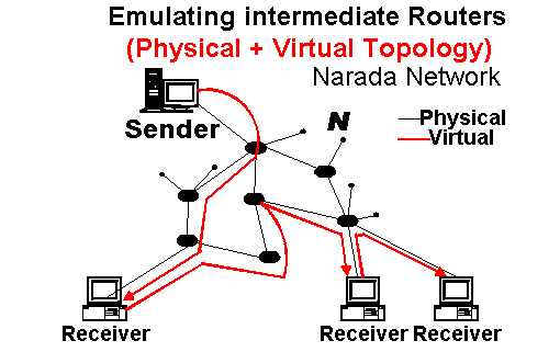
- By emulating intermediate routers
In this scenario we incorporate intermediate routers. The main reason for doing that is to provide a more realistic scenario since the whole network will be deployed over a LAN where "physically" no intermediate routers get involved.
As you may see from the following figure, all the black nodes in the figure are routers while narada members
are represented by the Receiver machines. In order to implement this scheme you need to implement both a standard routing algorithm among the routers (which will run only among the "black" nodes) + the narada
protocol which will run on the receivers(members) machines. This implies that you should implement & maintain 2 kinds of routing tables. We won't discuss this approach any further but if you really want to go with this approach come and find me. I will be able to provide with more info.
- Without emulating intermediate routers
This is actually the approach we suggest you to go with. The main difference in this approach is that you just consider the virtual multicast topology without any intermediate routers.
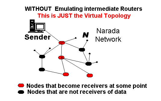
You may see from the figure that all nodes are the same thing (have the same implementation) but they may have 2 roles.
The first role is that they act as routers (they forward narada packets) and the second role is that they actually become receivers at some point. Suppose a scenario where you get some 16 nodes connect to each other and a fraction 25% (4 nodes) become randomly receivers.
These receivers will basically initiate a
<JOIN IP:PORT_of_sender_which_is_prespecified>.
Recall that this node knows which is the shortest path the Sender (since it maintains some routing tables which are updated by the REFRESH messages). It will consequently send the join message ONLY through the neighbor which will lead him to the sender through this shortest path. If the neighbor is already a receiver then no further steps need to be done since the neighbor will simply forward messages as they arrive from the Sender. If the neighbor is not a receiver , then the JOIN message must be propagated all the way up to sender, or until we find a receiver (in the path up to the sender).
Recall that Multicast and soft-state usually go together. So you need to send out from each receiver something like : <KEEPALIVE IP:PORT_of_sender_which_is_prespecified> every e.g. 20 seconds. Otherwise the parent node will stop forwarding messages.
|
You may have mentioned that the paper indicates 3 kinds of topologies.
- Waxman Model of 1024 nodes (routers) and 3145 links
- Mapnet 1070 routers and 3170 links
- ASMap (Autonomous System Map) of 1024 routers and 3037 links
Other possible topologies might be:
- Random with bounded Outdegree, where each nodes connects to min=0 and max=K random nodes. The only constrain is that each node connects to log(base=2)N nodes, where N is the total number of nodes.
Having this constrain your graph won't be disconnected (partitioned in 2 or more segments). Eg if N=128 you need to have K=7
- Power-Law, In simple words "a few hosts have a high-degree (connected to many others) and many hosts have small-degree".
The ASMap is in fact Power-Law (according to the following reference.
Michalis Faloutsos, Petros Faloutsos, and Christos Faloutsos. On power-law relationships of the internet topology. In SIGCOMM, pages 251-262, 1999.
Well why would you need an initial topology anyway?
The discussion that follows will help you to understand this point.
Well suppose that you have implemented the narada nodes along with all kind of features
such as Improving the Mesh quality, providing Data Delivery and so on.
What you still need is a boostraping mechanism.
The bootstraping mechanism will launch the nodes and tell each node where to connect to.
The following examples will show you how to cope with this problem.
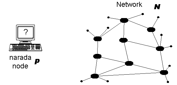
Node p doesn't know where to connect to because it has no
information about the IP addresses of the other nodes.
|
|
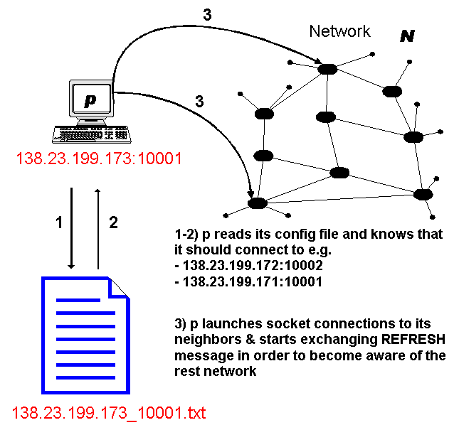
Node p consults its config file, which by the way is stored in some known place on the filesystem (e.g. /yourproject/conf/).
It then launches connections to these hosts ONLY. One important point is that p doesn't know anything else (i.e. about the rest nodes).
It only knows about its direct neighbors at this point. Eventually it will become aware of the rest network since after establishing the initial connections, nodes start exchanging REFRESH message (which will also contain info about hosts other that the direct neighbors
|
|

|
p's config file could look like the following example:
							# Narada Node configuration file

							# This file was automatically generated by topologygen (this is your topology generator)


							# These are my settings.

							# Upon initialization a narada node must make sure that

							# these are the settings that it is going to use.

							id=node1

							ip=138.23.199.173

							port=10001


							# Other narada nodes that I should connect to

							node2=138.23.199.172,10002

							node15=138.23.199.171,10001
|

|
Most of you may already realized that topologygen is the Topology generator we where talking about.
topologygen takes as an input a file like <topologygen.conf>, generates
a random topology and dumps the result into /yourproject/conf/. In this way an individual config file for each narada node is generated. You could of course write everything into a single file but this is really up to you to decide.
|
							# MAKE SURE THAT ConnectionPerNode >=  log2(#NetworkSize),

							# so that it is a fully connected graph

							# e.g if you are going to have 16 nodes log2 16 = 4

							# This implies that each node should connect to maximum 4 others


							# How many narada nodes should I create

							NetworkSize=16


							# How many connections per node (the max degree of each node)

							ConnectionPerNode=4


							# The IPs that should be used. These are the machines that are available

							# at the time you run your experiment. If you switch over to different machines

							# at some later point just regenerate a topology with the new machines set

							# This is convenient because in this way you may run your

							# network on any number machines without changing your code.

							IPs=138.23.199.171, 138.23.199.172, 138.23.199.173


							# The port from where the counter will start

							InitPort=10000
|
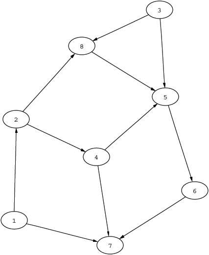
In the previous paragraph we described the topology generator and we understood that it is used as the bootstrapping mechanism. The topology generator might also be used in order to create some visualization of the initial network.
Consider for example the following table which by the way is pretty obvious and which can be generated while you are dumping the narada node configuration files.
It shows which nodes should connect to which others. Sockets by the way are bi-directional, which means that you may send and receive data through them. So the arcs only show who will launch the socket connection (because only 1 of two neigbors will actually do that). Once you have a link you may either send or receive along that socket.
Please mention that we don't ask you to do any visualizations. We just provide you with a pointer on how to do them since they may help you to debug your system. (i.e. see if messages are routed along the correct links)
|

|
						# Download GraphViz and

						# Compile with : "neato -Tps narada.dot.txt > narada.ps"

						digraph narada {

							size="7,8";

							ratio=fill;


							1 -> { 2; 7; }

							2 -> { 4; 8; }

							3 -> { 5; 8; }

							4 -> { 5; 7; }

							5 -> { 6;  }

							6 -> { 7;  }

							7 -> {  }

							8 -> { 5;  }

						 }
|

|
|
|

