{ [ ] Projects >>> [Hardware] - [Software] - [Class] - [Other] - [Failed] -|!|!|- [Resources] - [Biography] - [Contact] - [ ] }
Control a DSLR Camera
Wirelessly with the Propeller and XBee
Abstract
This is a short guide on how to set up a system that uses two Propeller chips, at least two XBee modules, and a Canon DSLR camera to wirelessly focus and release the shutter on the camera.
Notice
A warning before we begin: you take all risks associated should you choose to follow these directions. I can’t be held responsible if you somehow manage to destroy or damage your $700 camera. Make sure that you double check all the sources, and understand that mistakes happen. Your camera (and other goods) are your responsibility. Other camera brands may not have the same wiring. I used a Canon for this example.
Introduction
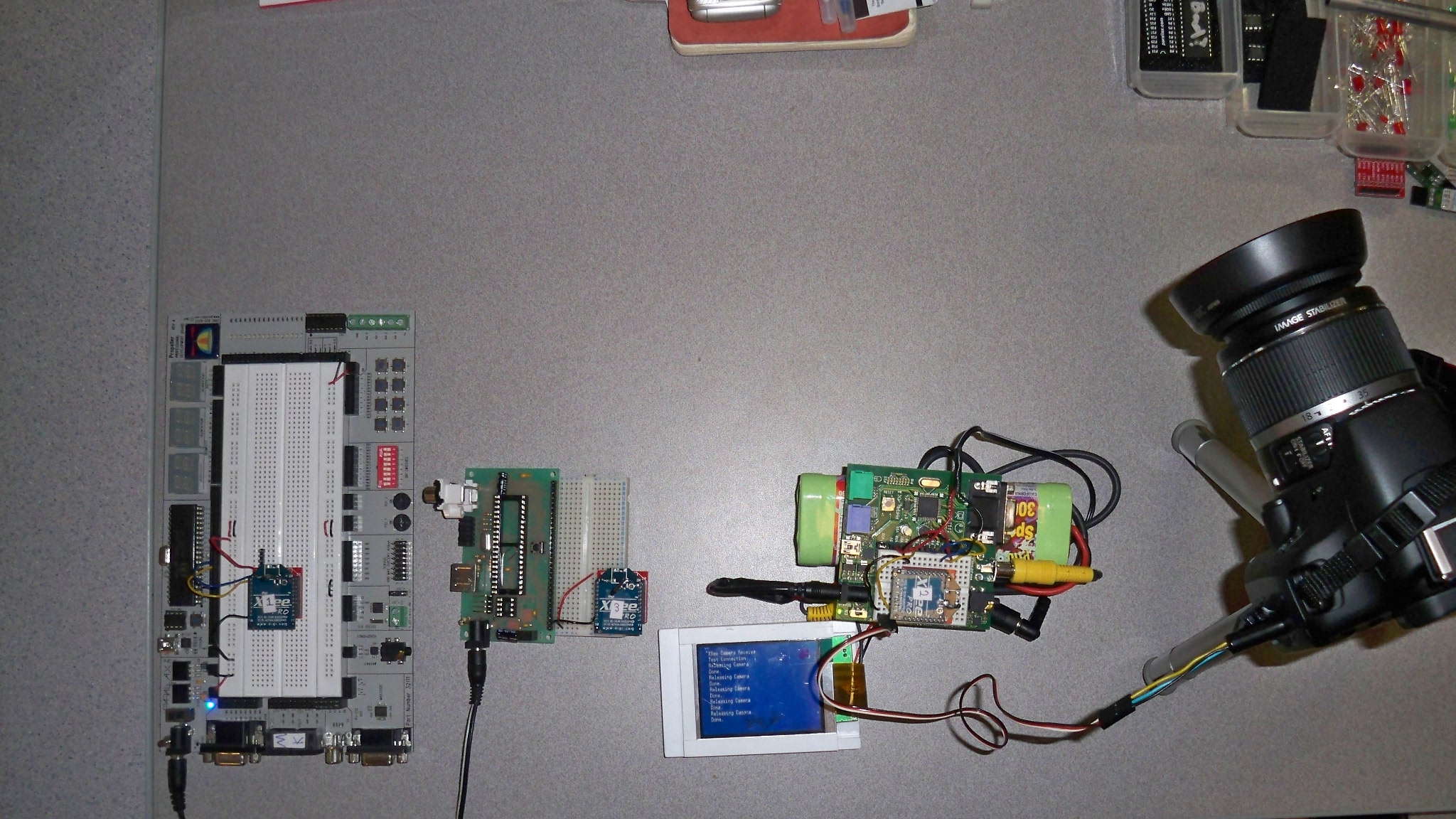
I wanted to build my own wireless control system to control my camera from afar. My requirements dictated that the system should be extensible (aka, multiple radios strategically placed to extend the range), easy to set up, and able to provide feedback on the camera release. This is all possible with the XBee radio transceivers and two Propeller microcontrollers.
The XBees are loaded with the Digimesh firmware. Digimesh was chosen over the preloaded firmware or Zigbee because of the ease of use and the ability to autonomously build a mesh network. The preloaded firmware doesn’t seem to support drop in mesh networking, with Zigbees require coordinators and routers. The main disadvantage with the Digimesh is that it doesn’t support tying I/O lines between two modules. I used three Series 1 XBee Pro modules for this system. One module is at the transmitter Propeller, one module is at the receiver Propeller, and one module acts as a relay to extend the range.
Setup
To setup each Xbee follow these steps. The XBee should be connected to a serial or USB port on your computer. I used a Prop Plug to program mine, and an adapter board from Sparkfun to break out the pins on the XBee.
- Using X-CTU, select the correct COM port and click “Test/Querry”.
- Make sure the popup dialog says that communication is okay.
- Click the “Modem Configuration” tab.
- Click “Read”.
- From the leftmost drop down list select XBP24-DM
- Under “Networking”, select the “Modem VID” and enter your own PAN ID.
- Under “Addressing”, set “DH” to 0 and “DL” to FFFF
- Save the profile for ease of use later.
- Change the “Node Identifier” to a number of your choice. Make sure to get rid of the leading space.
- Click “Write” and wait.
- Repeat for each Xbee, but note that you can load the profile for most of the settings. Just remember to give each XBee a unique Node Identifier.
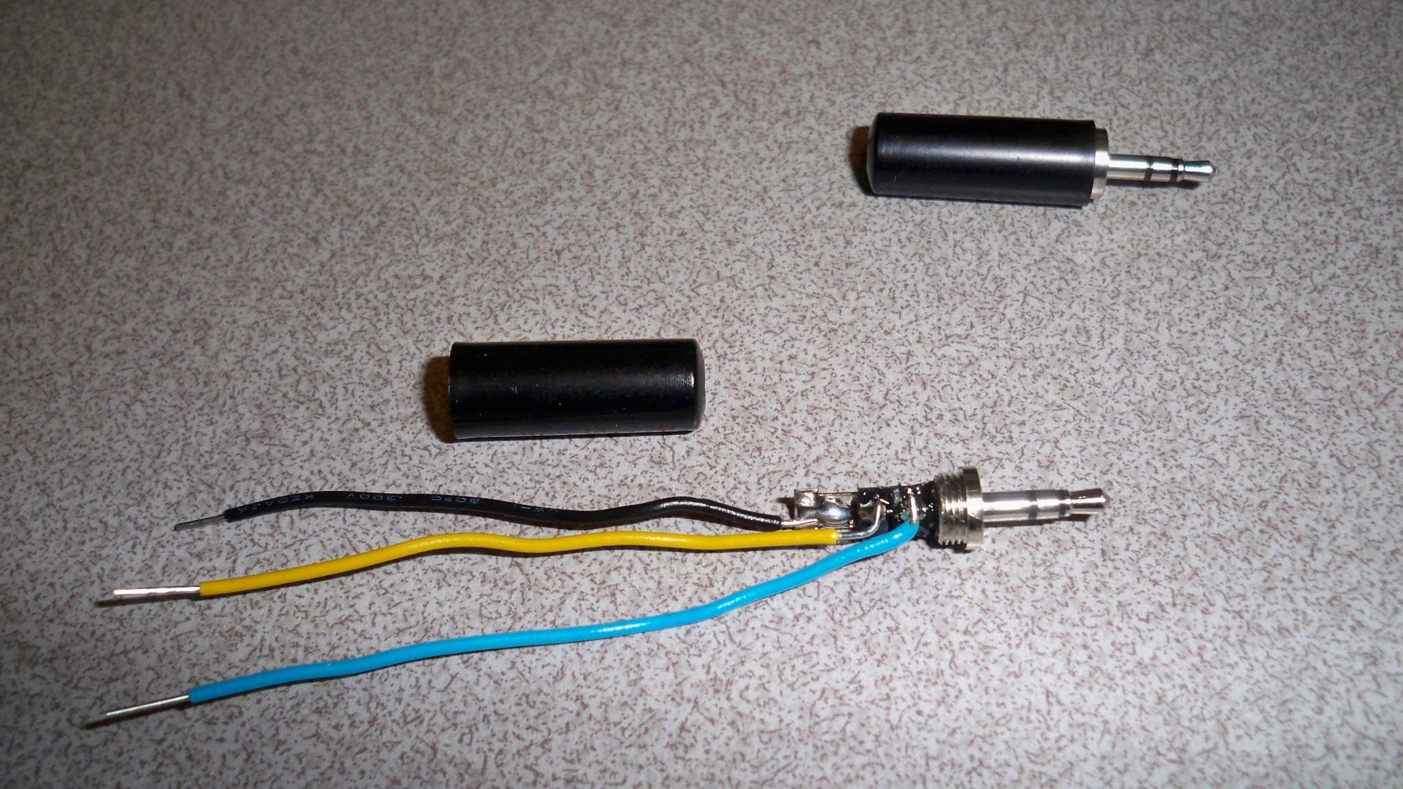
The Plug has three wires soldered to it, although only two are used in this design. The plug is a 2.5mm stereo jack. The tip is expose, the ring (middle) is focus, and the sleeve (ring on wire end) is ground. The expose automatically focuses before exposure, so the focus isn’t always needed. To activate the Propeller pulls the line low on the expose wire, which is equivalent to pressing the shutter button all the way. More information on the plug can be found here: http://www.covingtoninnovations.com/dslr/CanonRelease.html
Once everything is built it’s merely a matter of programming the Propellers and testing it out. Note that the camera should be connected after the receiver is turned on and running, since the Propeller starts out with low pins (which would release the shutter).
Transmitter code:
CON |
Receiver Code:
CON |
From Here
Future steps could include a confirmation message from the receiver back to the transmitter to indicate a successful picture, a button on the transmitter to manually release the shutter, and a function that indicates network status to make setting up a reliable connection easier.
Attachments
(Right click and "Save Link As...")
XbeeCameraReceive.spin
XBeeCameraTransmit.spin
(c)2010 Cody Lewis
lewisc@cs.ucr.edu